
UAV / Drone (Aerospace) Cable Assembly Considerations

UAV, RPV & Drone (Aerospace) Cables
Aerospace cables are used in a variety of applications including data, fiber, Ethernet, power, video and more. Cables for aerospace applications must be prepared in a unique manner in order to comply with environmental, weight, aging, and safety requirements. Weight is of particular importance since large aircraft can require over 100 miles of wire weighing more than 3000 pounds. The lower the cable weight, the more economical the aircraft fuel consumption is, along with greater speed potential.
Aerospace Cable Considerations
- Weight: The weight of an aircraft cable can be reduced by utilizing wires with a higher temperature rating. These wires require less copper and hence weigh less. Another method of minimizing weight is to incorporate improved insulation.
- Environment: There are a variety of environmental considerations to account for including temperature, exposure to fluids, moisture, vibration, and pressure.
- Flammability: It is important that aircraft cables emit minimal smoke and dangerous gases if they are exposed to fire.
- Ease of installation: Aerospace cables must be easy to cut, strip, mark and terminate. They must also be flexible to allow for conduit routing.
- Overload conditions: The cables must be able to maintain circuit integrity in case of a current overload situation.
- Wireframe abrasion: Aerospace cables must be resistant to abrasion from surrounding conduits. Abrasion can be magnified with aircraft vibration.
- Surface properties: Cables must be able to be clearly marked, must be smooth, and receptive to label adhesion.

Aerospace Cables and EMI
Aerospace cables must adhere to specific Electro Magnetic Interference (EMI) requirements. Aerospace cables should follow these guidelines:
- Provide sufficient grounding at both ends of the cable to chassis ground.
- Shield the cable signals and minimize the transfer impedance (The voltage that develops on the other side of the cable surface due to the cable signal current).
- Minimize the use of braided shielding and instead use foil.
- Twist data signal wires which will help to cancel out emission fields.
- Use filtered connectors
Aerospace Cable Failure Modes
Care should be taken in the cable design to avoid failure modes which include the following:
- Aging: The wiring insulation can degrade with time. This happens when the electrical insulation dries out and becomes brittle. The insulation can then crack with aircraft vibration.
- Arc tracking: Arc tracking occurs when there is an electrical current along the insulation coating instead of just the wire conductor. Heat generated by the current flow causes a breakdown of the insulation material.
- Flash over: Once initiated, arc tracking can grow with time resulting in an arc across adjacent wires and the insulation material starts to burn. This occurs especially with Kapton wire which is now not permitted in aircraft wiring.
- Chafing: Chafing occurs as wires vibrate and rub against each other or against the aircraft structure.
Aerospace Cable Specifications
There are a variety of specifications that can be imposed on the design of an aircraft cable. In some applications the cable manufacturer must subject sample cables to various stress tests in order to prove that the specifications can be met. Some of the specification standards for aerospace include:
- BMS: BMS stands for Boeing Material Specification. These cover a variety of cable types including data bus and fiber.
- M27500 and M22759: These are military grade specifications used for aerospace cables. Many more MIL spec variations can be required depending on the application.

Loose Cable Responsible For Faster-than-Light Neutrino?
Recently, the case when scientists at CERN were left puzzled over neutrinos that appeared to travel faster than the speed of light. The findings were controversial because they conflicted directly with the theory of relativity, as well as virtually everything else we know about the way the universe functions. Ever since the results were released five months ago, scientists at both CERN and other institutions have worked to explain the results. It was believed that all potential errors had been eliminated. That is, until they checked their cables.
“Until They Checked Their Cables”
As it turns out, a fiber optic cable was distorting the results produced by one of the atomic clocks that was timing the neutrinos experiment. This loose cable caused the readings to appear slightly faster, making scientists read the neutrinos as being faster than the speed of light. Although only one source has reported this finding, it’s a sound explanation for a phenomena that was otherwise bordering on impossible to explain. This is an error that took almost half of a year for the world’s top scientists to find. The manpower, time and money that went into finding this error could certainly have been better invested in other areas. Instead, something as simple as a loose cable resulted in a black hole of productivity.
The issues seen in this experiment underscore that the cable & wiring details should never be overlooked whether its trying to figure out that plugging the RCA component cables in the wrong sequence threw out all the colors on your TV screen or when operating something of a large scale or of serious consequences. Suppose that the same thing happened not in a controlled experiment, but in an industry where the potential for danger is high. Cables with intermittent connection in high reliability industries can certainly be responsible for a host of interesting consequences. In a commercial or industrial facility, intermittent connections could lead to inaccurate temperature and facility readings.
Beyond these sorts of catastrophic failures in scenarios where a finished product is being used, loose or improperly installed cables can also make the results distorted in research environments. In industries, where new equipment and technologies are being tested, engineers and technicians rely on testing equipment to interpret readings. This is exactly what happened in the CERN experiment, but again, the results could be more devastating if the issue isn’t taking place in a controlled environment. Imagine the military commissioning a new jet that was designed based on faulty research due to loose aviation cables. The losses would amount to millions of dollars before anyone caught on to the flaw.
Situations like what happened at the CERN research facilities just prove that it’s never safe to overlook thorough inspection of even the most minor components. High-reliability industries just can’t afford the risk, especially if the system lacks redundancy. When constructing new equipment, the use of quality custom cables that are tailored to meet specifications is crucial. Properly manufactured cable assemblies customer specified and customized specifications means that the results being reviewed by engineers will be accurate every time. On the other hand, poorly built cable assemblies result in lost time, lost money and potential weeks of frustration.
Further Reading: Ars Technica
Flexible vs. Semi Rigid vs. Rigid RF (Coax) Cable Assemblies
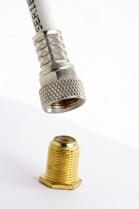
RF cable assemblies are made up of coaxial cable with appropriate connectors attached to the cable ends for interconnecting what are usually defined as signal sources and receivers. The Coaxial cables used are usually defined as flexible, the most common, semi-rigid and rigid with some hybrid cables such as “formable” cables that lie somewhere between flexible and semi-rigid and are usually applied to semi-rigid cable applications.
By definition a coaxial cable consists of an inner signal conductor that is surrounded by a tubular insulating layer (dielectric). A tubular conducting shield then surrounds these components. In this design the inner conductor follows the same geometric axis as the outer shield, or the inner and outer conductors are in a coaxial arrangement. Depending on the application a protective, non-conducting sheath is placed around the outer conductor.
Most commonly RF coaxial cables are used to form computer network (Internet and Ethernet) connections, distributing cable television signals or to connect RF transmitters and RF receivers with their antennas. When a voltage (signal) is applied to the center conductor and the shield is kept at ground (zero) potential, the design of the coaxial cable provides a transmission line where the electromagnetic field carrying the signal is limited to the insulated space (dielectric) between the inner conductor and the outer conductor or shield.
One simple advantage to this isolation is the allowance of installation of a coaxial line next to metal objects without power drainage. Additionally, the coaxial design provides protection of the RF signal from external RFI (radio frequency interference) or other EMI (electromagnetic interference). Consequently, coaxial cables are a good choice for weak signals that cannot tolerate interference and, conversely, for higher power transmissions that can cause interference to adjacent instrumentation.
Flexible Coaxial Cable
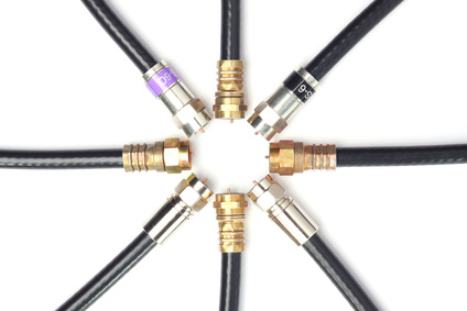
Probably the most common coaxial cable is the simple flexible coaxial cable commonly used by the layman to connect video equipment. This cable consists of a metal inner conductor, a flexible plastic polymer dielectric tube surrounding it, a braided/woven conducting metal shield around the dielectric and finally a jacket to protect the interior from environmental damage such as moisture, puncture and abrasion or breakage of the shield.
For extreme flexibility, a stranded copper central conductor is used with a surrounding dielectric tubing of PE (polyethylene) foam that is then surround by an Al tape outer conductor combined with a tinned copper braided shield.
When less flexibility is needed, somewhat higher performance characteristics are obtained when solid wire (bare copper, bare copper clad aluminum) or even copper tubing is used as the inner conductor. For higher frequency performance, the inner conductor may be silver-plated such as SPCW (silver plated copper wire) or silver plated copper clad steel. Braids and foils may also be silver-plated.
As an alternative to PE foam, more water resistant but less flexible solid polymer dialectrics such as LD PTFE (low density polytetraflouroethylene) are used. Cables can be jacketed with smoke retardent PE polymer coatings. The highest fire resistant rating is given to cable jacketed with FR PVC combined with PTFE dielectrics.
One of the disadvantages of highly fexible coaxial cable is the use of a braided shield that is not a smooth surface and bending causes variations in the actual electrical characteristics of the cable. Very sharp bends or even kinking of the shield can seriously affect transmission power and integrity. Similar results occur from bending of the stranded inner conductors. A solid conductor with a coating to smooth the surface and the use of a film shield within the braided shield are improvements but not ideal.
Semi-Rigid Coaxial Cable
To obtain better overall performance characteristics and dependability and maintain the concept of a coaxial cable designers have had to sacrifice flexibility. Semi-rigid designs provide better dielectric properties and shielding quality. Probably the most important difference between flexible and semi-rigid coaxial cable is that the braided outer or film shield is replaced with a solid metal outer sheath which has is bendable but flexible. Once formed (bent) the cable’s configuration is fixed.
Compared with a braided outer conductor, the solid shield provides superior performance especially at higher frequencies. In fact, the outer conductor can provide 100% RF shielding and allows precise spacing of the solid center conductor and surrounding dielectric. Outer sheaths can be solid bare copper, tin-plated copper or lighter (30%) tin-plated aluminum. Center conductors are commonly silver covered copper clad steel or SPCW. PTFE or LD PTFE tape is a common dielectric.
The semi rigid coaxial cable design providing the best electrical performance consists of a central conductor supported by a solid PTFE dielectric spline placed longitudinally inside a solid metal tube. These “Spline Cables” are fully vent-able and when mated to vented connectors they can be filled with air, other gases or operate in a vacuum as in spacecraft. They are expensive and require special care to bend and install. A copper tubular sheath lined with the dielectric PTFE/Air spline supporting a SPC tube center conductor is a common form.
Conformable or Hand-formable cables could be termed semi-flexible rigid-like cables and provide a choice when formation of the cable must be done at the point of installation. They can be cut, stripped and formed by hand. However, they are not intended for repeated bending. A solid tin plated aluminum shield, LD PTFE tape dielectric and a SPCW center conductor comprise a typical structure.
Rigid Coaxial Cable
Rigid coaxial cable is formed by two copper tubes supported at cable ends and at meter intervals with PTFE-supports and cannot be bent and require specially constructed elbows (45° and 90°) for turns/angles. Interconnections must be achieved with an inner bullet/inner support and a flange.
Rigid line coaxial cable is mainly used indoors for high power connections between RF-components in TV and FM broadcasting systems although the rigid line cables are used outdoors in antenna masts. Inner conductors are copper while outer conductors are either copper or aluminum for cost and weight savings.
Rigid vs. Semi Rigid vs. Flexible Coax (RF) Cable Assemblies
When outlining the benefits of rigid cable in comparison with semi-rigid or flexible coaxial cable it is in most ways a comparison between apples and oranges. Semi-rigid cables simply cannot come in the sizes necessary for high power applications involving TV, FM and many microwave frequency wireless transmission over significant distances. Semi-rigid cable sizes are limited for most applications to a 1/2” air filled spline semi-rigid cable with copper tube inner and outer conductors – a mini rigid cable – that is extremely difficult to bend are limited to GHz frequencies. Additionally, power-handling capabilities are measured at a few hundred watts.
Rigid cable comes in sizes ranging from 7/8” to 8 3/16”diameters, operate at TV and FM frequencies ranging from 800-60 MHz and have power capacities measured in 100s of KWs up to a megawatts and above. Sizes of 6 1/8” and above allow for multi-channel DTV/analog transmission. Elbows solve the problem of flexibility, and systems may be filled with dry air or inert atmospheres under positive pressure for outdoor use. Additionally, the newest designs do not require periodic maintenance and lifetimes are measured in decades.
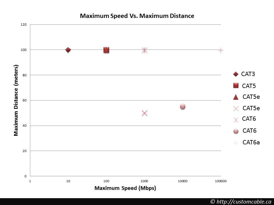
CAT3 vs. CAT5 vs. CAT6
CAT3 vs. CAT5 vs. CAT5e vs. CAT6 vs. CAT6e vs. CAT6a vs. CAT7
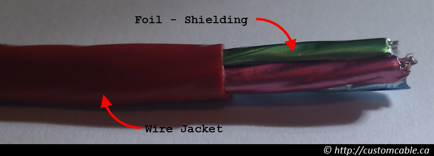
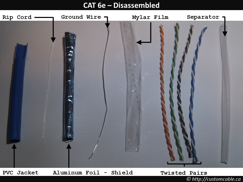
While the consumer electronics keep going increasingly wireless, many LANs still rely heavily on CAT cables to handle all the heavy lifting when it comes to transmitting data. To begin with, all Ethernet cables are of two key varieties i.e. UTP (unshielded twisted pair) or STP (Shielded twisted pair) variety. They all have the same construction structure, but vary a great deal as far as transmission frequency and throughput are concerned. However, some terms need to be defined before any meaningful comparison can be presented:
How to interpret Ethernet cable Speed?
- 10 Mbps = 1.2 MB / s i.e. 1 hour to download a DVD (4.5 GB)
- 100 Mbps = 12 MB/s i.e. 1 hour to download 10 DVDs (assuming 4.5 GB average)
- 1.0 Gbps = 125 MB/s i.e. 1 hour to download 100 DVDs (assuming 4.5 GB average)
- 10 Gbps = 1.25 Gbps i.e. 1 hour to download 1000 DVDs (assuming 4.5 GB average)
What is Frequency?
Imagine you can only drive two cars, one passenger each, at a given time on a highway in each of the two lanes. Now you would be able to transfer more people over the same highway if you can drive the same two cars 500 trips per day compared to 250 trips per day.
Now imagine the same analogy but replace cars with bits of data. So if you can only drive two bits on a given data-line then 100 Mhz (or 100 million cycles per second) will give more bandwidth (i.e. ability to transfer data over the same line) then 50 Mhz (or 50 Million cycles per second).
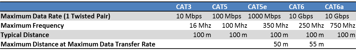
 UTP and STP Comparison Chart
CAT3
The Category 3 or CAT3 standard was used heavily in the early 90’s for wiring offices and homes. It’s still used in two-line phone configurations, but has largely fallen out of favor for wired networking thanks to the Category 5e cable’s superior performance. CAT3 can be relied on to handle data speeds of up to 10 Mbps, but no more. Its maximum frequency clocks in at 16 MHz. Like many other cabling options, it relies on copper for data and power transmission. While theoretically limited to 10BASE-T Ethernet, it can actually support 100BASE-T4 speeds by using 4 wires instead of 2 to achieve 100 Mbps throughput.
CAT5
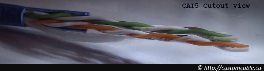
Around 2000 or so, CAT5 overtook CAT3 as the Ethernet cable of choice for LAN networking. CAT5 uses either the 10BASE-T or 100BASE-T standard for data transmission. Using two cable pairs to signal over copper wire, CAT5 is now largely archaic and isn’t widely used for Ethernet connections. It’s rated for a maximum frequency of 100 MHz and top speeds of 100 Mbps. CAT5 uses 8P8C modular connectors to connect devices together, and can be used effectively at lengths of up to 100 meters. Today, CAT5 cable has been replaced for the most part by CAT5e.
CAT5e
While very similar to CAT5 in appearance, CAT5e introduces some new wrinkles in the equation. For one thing, CAT5e uses four pairs of copper wire rather than the two that CAT5 relies on. In addition, the wire pairs are twisted more tightly and are sheathed in heavy-duty shielding to eliminate crosstalk. Crosstalk cuts down on the speed at which a cable can transmit information. Thanks to its internal upgrades, CAT5e is capable of achieving 1000BASE-T speeds. In other words, it can handle up to 1 Gbps of throughput at a distance of up to 100 meters. As of today, it’s the most common type of cabling found in modern homes and offices for Ethernet purposes.
CAT6
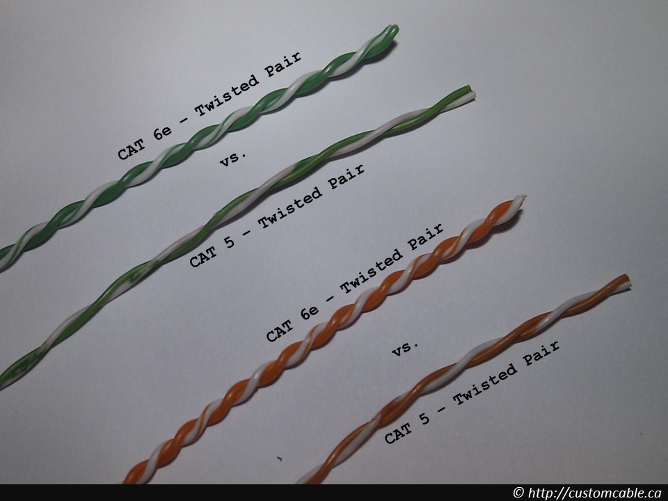
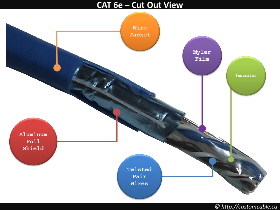
For back-end, high-capacity networking, CAT6 supports Gigabit Ethernet needs. Supporting frequencies of up to 250 MHz and the 10BASE-T, 100BASE-TX, 1000BASE-T, and 10GBASE-T standards, it can handle up to 10 Gbps in terms of throughput. Thanks to better cable insulation, CAT6 reduces potential crosstalk even more so than CAT5e. When used for Gigabit Ethernet and below, the maximum allowable cable length is 100 meters. For 10GBASE-T speeds, the maximum cable length is 55 meters. The one major caveat of CAT6 cables is that installation can be tricky, as compatibility with 8P8C requires the use of special adapter pieces for optimal performance.
CAT6e or Enhanced CAT6
These are an enhancement on the standard CAT6 cables, as they perform much better when installed in an environment with high noise or RF interference. While better than CAT6, they are not as good as the CAT6a or CAT6 Augmented standard cables.
CAT6a
If you’re wiring up your home or office for Ethernet for the long haul, CAT6a is the perfect choice in terms of future-proofing. When it comes to A/V protocols, CAT6a is supposed to replace HDMI in the coming years. The main difference between CAT6a and CAT6 is that CAT6a can operate at a frequency of up to 750 MHz. In addition, CAT6a is even less susceptible to interference and crosstalk. The improved specification and shielding allows CAT6a to provide more consistently reliable speeds in difficult environments. Thanks to its performance and stability, CAT6a is the preferred cable for 10GBASE-T Ethernet.
Cat 7 and Beyond
The list of Ethernet options doesn’t stop at CAT6a. There’s also a version called CAT7 that’s even more capable than all of the TP cable variants listed above. CAT7, also known as Class F cable, supports transmission frequencies of up to 600 MHz. It supports 10GBASE-T Ethernet over a full 100 meters, and it features improved crosstalk noise reduction. While CAT6e is the current standard when it comes to 10GBASE-T, it will inevitably be replaced with CAT7. Nobody knows what the future holds for Ethernet cables or what will come next in terms of format or performance. No matter what happens, expect faster and faster cables with each passing year as the technology and protocols that support Ethernet continue to improve. Finally, one thing to always keep in mind is that any custom cable can be built to suit the application on any project.
Wired vs. Wireless Connections
Author’s note: While I have tried to keep any personal bias out of this post but it should still be read in the context of the idea that we would like to be preferred vendor for cable assembly and wire harness development and manufacturing.
The debate between using wireless or wired devices and networks often comes up in a few different contexts. Whether it is a personal Internet network for a home or in commercial applications like a wireless ECG/EKG monitor, technology has made it possible for numerous wireless items to reach the market. There are many business internet services out there, Primus is one example The question is whether wireless or wired options are better for the needs of the individual or company.
Comparison for Personal Use:
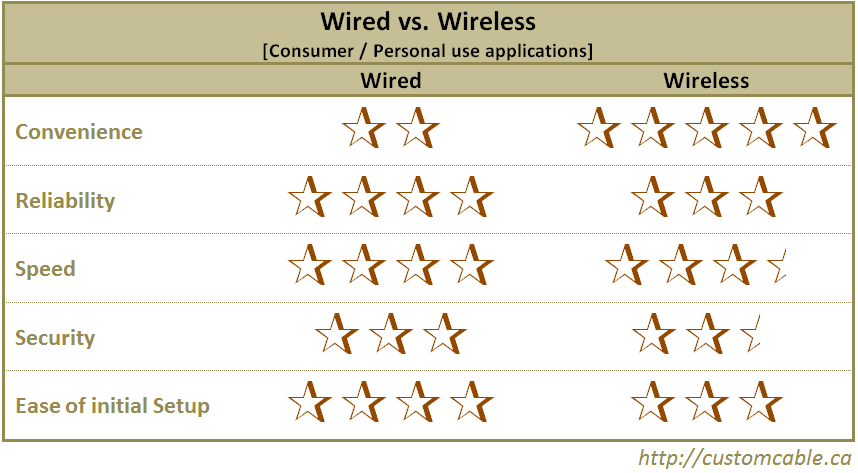
The use of a wireless router and a wireless system in a house or for personal devices like phones, MP3 players or similar portable electronics is a long-term trend. In personal use, wireless and wired options are often related to Internet usage. Both options, wired and wireless connectivity have their advantages and disadvantages that appeal on a personal level.
One of the first considerations is the level of convenience. In the case of convenience at home or on the road, wireless options are often the most convenient choice. Wireless networks can be accessed from any computer in the vicinity of the router, making it possible to connect several computers in one house. Another advantage is the ability to use wireless chargers and wireless devices while on the go. A wired connection is less versatile in personal use, so when it comes to convenience the wired options are at a disadvantage.
Security is another consideration with wired and wireless networking. In this category, wired networks are generally better because the security built into the system is better than a wireless option. Wireless will require taking some additional measures to secure the connection. That said, many wireless routers in the market today offer security settings at the click of a single button mounted on the front panel of the router or the switch. All too often, it would users own actions (visiting sites with malicious software and viruses, opening suspect emails, putting credit card information on unsecure webpages etc.) that will compromise their security before someone breaks through their WEP or WPA encryption.
Reliability is another feature to look for when determining whether to use wired or wireless connections. In the case of reliability, wired connections are generally best because interference is not an issue and speed remains steady as a result of the wire. With wireless networks one can casually walk in and out of the wireless’s range, often resulting in a dropped connection. Overall, the wireless connections do tend to be a little more fickle, often for reasons that the end user may never fully resolve.
Wired connections (@ 1000 mbps) remain at least three times faster than their wireless counter parts (@ 300 mbps) at least at the time of writing this article. Although this should have little to no impact on most end users since most residential broadband internet providers offer speeds well below the 300 mbps and at the same time, there is nothing stopping the end use from connecting their computers to the modem on as and when required basis.
In the area of personal use, wired devices have an advantage of being more secure and reliable than a wireless option. Unfortunately, in this area convenience will often outweigh the advantages of the wired options.
Comparison for Commercial Use:
While personal Internet usage and personal devices might use a wireless network, when it comes to commercial needs the determination of which system is better varies on different opinions and the needs of the products. Understanding the advantages and disadvantages of each system can make a difference between which system is better. In the case of commercial usage, or the use of commercial devices, the advantages and disadvantages might seem surprising.
One of the major considerations is the cost associated with a wire harness versus a wireless option. The wired device is infinitely less costly to develop and make, thus it is ultimately less costly to buy. When making commercial devices it is much less costly than putting together the components of a wireless system. The wired system has a clear advantage over the wireless when it comes to price, especially of the device is for a custom application and low volume.
Another consideration with wired and wireless commercial devices is the reliability. Since wireless will often have interference from other devices, the wired system is clearly superior in this instance. The design engineer or the developer would have one less variable to accommodate if they take the wired route. At the same time the designer can concentrate on the task at hand rather than spending time and resources on making a wireless system work, as well as meeting any regulatory requirements from independent bodies such as FCC. Commercial devices frequently require very reliability built into the system. The risk of losing the connection, or just degraded performance due to interference from external sources makes wireless options less advantageous.
As with any other system, wired connections are more secure than wireless options. In a commercial device, this security might make the difference between losing valuable data on the device or keeping it safe.
In commercial systems, a wired device is clearly superior to the wireless system because of the ease of product development; reliability; reasonable cost and security outweigh any minor convenience a wireless option might provide.
Comparison for Industrial Usage:
When considering whether to opt for wireless or wired solutions in an industrial setting, the factors are often different from personal usage or commercial usage. Using wired connectivity is sometimes the only available choice due to the fact that many industrial devices might not be economical to build and set up on a wireless interface.
The first consideration related to industrial devices is the development cost of wireless. Industrial devices often require the use of custom cables and wire harnesses to allow the items to work effectively. In many cases, the cost of trying to develop a wireless system that will work integrate with the existing setup could be substantial. Often, there would lie more value in adding additional features in the same budget as opposed to making an effort on reliably and securely transmitting data over the wireless. Off course here the assumption is that any such system will need to transmit the data or I/O signals in real time; often attaching laptop to such a system and re-relaying the information over the wireless would make more financial sense.
The effectiveness of the equipment is another key point that industries must consider before looking into wireless options. As with any other system, a wireless device made for industries will have the limitations of any other electronic or similar item. The problem with this is the fact that the system might have interference that makes equipment stop working when it is on a wireless system. That can result in costly delays for a production line as then the line or system would be down or the data will be buffered all the while the cause of failure and a resolution is being determined.
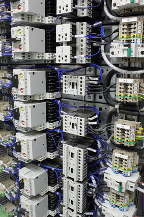
Industries need reliable systems and many items like a programmable logic controller or current testers cannot afford the potential reliability problems that may be introduced with the wireless option. A PLC in particular is not worth creating as a wireless system because interference from common devices like cell phones might even put lives in danger as might happen if the PLC system at an amusement park suddenly lost the connection as there was one more variable for its proper operation.
Another factor that industries must consider is security. Poor security in a wireless system can be complicated to manage on the large scale of industrial equipment or computers. This can not only become expensive, but it can result in problems like viruses that ruin the system. A cable assembly is by design more secure, so the system is easier to keep from any security breaches.For industrial use, a wired system is a better option than trying to develop wireless options. The cost of traditional wire harness options, custom cable needs and cable assembly combined with the reliability and security makes a wired system the obvious choice for industries. Wireless is not an option when it can result in danger and potentially expensive delays.
The choice between wireless and wired systems is often a matter of using common sense and weighing the pros and cons. In a personal home or individual devices, a wireless system might be the most convenient and does not have the risks of commercial and industrial equipment and devices. For those looking at a commercial device or industrial systems, wired options are generally the better choice as a result of better safety and reliability. Lets not forget that some situations can be totally unique to a point that people will try any approach for a fast data transfer, as was the case with South African company that used a pigeon to send 4Gb over sixty miles.
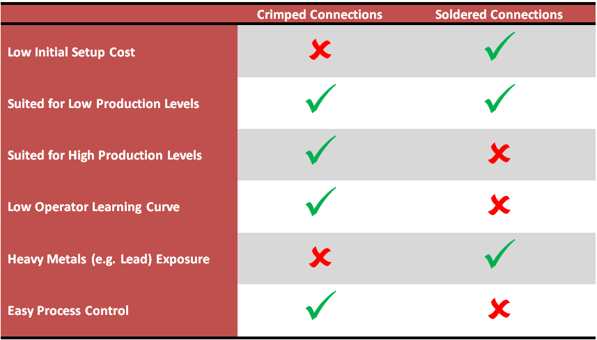
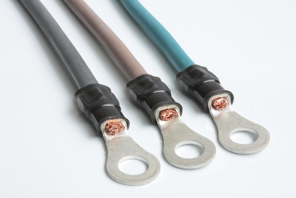
Crimping Vs. Soldering For Cable Assemblies
Cable assemblies can be produced either with the aid of crimped connections or soldered connections. The type of desired connection type is merely a matter of choice. In general, the trade off is between speed and reliability. It is possible to achieve reliable connections in the least possible amount of time through soldering, yet it’s also possible to obtain connections that may be slightly more solid via soldering. Both mass production and custom production have preferred methods, and both of these connection styles have their strong points and their weaknesses.
 Crimping vs Soldering For Cable Assembly
From a manufacturing perspective, the goal is throughput while maintaining quality. That almost definitely means that factory-made cable assemblies are produced with crimped connections. Making these connections is a simple as fitting the connector pins over the wires and using a reliably determined amount of force every time so that all pin connections are solid. The typical user will find that these crimped connections are secure enough for typical purposes. Cables for electronics purposes should never be placed under high tension or any other type of stress or strain. This might cause connections to come loose or wire insulation jackets to crack.
For those who need custom cables instead of the stock cable assemblies, whether to use crimped or soldered connections is simply a matter of choice. The reason soldered connections typically are not used in production environments is because of the time it takes to make each connection. Soldering requires heating the two metal surfaces to be mated so that the solder melts. This process requires special attention to detail. During the soldering process the wire insulation jacket should not become so hot that some of it melts and becomes trapped between the individual strands of wire. Also, concluding the soldering process, the solder flux has to be cooked out of the connection to ensure a reliable connection. For those who are proficient in their soldering skills, reliable connections can be achieved that are just as good as or even better than the crimped connections.
Soldering may also be an attractive option for those who only wish to produce a small quantity custom cables. Depending upon the type of connection, some of these crimping tools can cost nearly as much as the cable if not more. A soldering iron can be used for numerous projects, which brings down the cost of this job and many others, depending upon the life of the iron and the number of tasks. The decision whether to use crimped connections or soldered connections does not make a significant difference with regard to the useful life of the cable.
From the standpoint of longevity, either type of connection should last for the life of the user. However, given that most wires are made from copper, the soldered connection might provide slightly better protection against the corrosion that occurs just from normal open air exposure. Realistically, any resulting corrosion is slight, usually amounting no more to a native layer of oxidation. From a process perspective, crimping will always be preferred as the number of controllable variables are significantly less than soldering.
The terminals are standardized and will accept either type of connection. Whether these are custom cables or standard factory made cables, they should connect the same. From the standpoint of making connections to the terminals there is no significant difference. Using one type of connection over the other is merely a choice to be made at the discretion of the user. Crimped connections can be faster to produce, though soldered connections may provide a slightly more solid connection. Since both are equally capable of performing the same function, the real concern should be for the individual cable wires. These wires should be protected against stresses and strains that may cause the insulation jacket to weaken and even break.
PVC vs Polytetrafluoroethylene (PTFE) Wire Jackets
Based on the application, it may be difficult to pick the most suitable wire jacket. Often the choice boils to between Polytetrafluoroethylene jackets and PVC jackets. However, when the two types of jackets are compared, one will find that they are really quite different. One of the key differences between the two jackets is their price points.
When comparing the prices, it is easy to notice that Polytetrafluoroethylene wire is significantly more expensive than PVC wire. However, that is driven by the fact that there are many differences between PVC and Polytetrafluoroethylene wire. Each has its own unique properties, and can be used in different applications and project requirements.
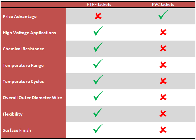
PVC, or polyvinyl chloride, is also known as vinyl. It is arguably the most dominant type of wire jacket available on the market. However, it is not designed for high-voltage applications. It is more suitable for low-voltage applications, and Polytetrafluoroethylene is usually better suited for higher voltage applications. PVC jackets are available in may different flavours for various applications. Additionally, PVC can differ as far as pliability and electrical properties go. Because of this, the prices off different PVC jackets can vary siginificantly. There are three different commonly known types of PVC. They include:
- Standard PVC, usually used for commercial and industrial applications. It is also used in computer and control wires applications.
- Semi Rigid PVC, tougher than the common PVC wire as well as the fact that its electrical properties are more stable, which means that it offers better protection then the first type.
- Indicated PVC, possesses unusually high resistance to abrasion. It should also be noted that it is also not thermoplastic.
PVC cables have good electrical properties that vary over a wide temperature range. Considering how durable and long lasting they are, for most applications they are fairly suitable. However, PVC wires do have some undesirable properties; for example, PVC wires should not be used in temperatures, which are above seventy degrees Celsius. Their thermal rating is limited. Also, it should be noted that the thermal decomposition of PVC has Hydrochloric Acid (HCI) as a bi-product.
Polytetrafluoroethylene has better electrical properties than PVC. It also has a higher temperature range and chemical resistance. Consequently, it is often refered to as high temperature wire. Unlike PVC wire jackets, which cannot be subjected to ultra-violet light for an extended amount of time, Polytetrafluoroethylene can. However, like PVC, Polytetrafluoroethylene should not be used in high-voltage applications. There are two types of Polytetrafluoroethylene wire:
- TFE wire jackets can be manufactured in long lengths because of the material from which it is made.
- FEP wire jackets can be manufactured in long lengths that are continuous. Additionally, they can be color coded for control applications.
Polytetrafluoroethylene offers significant number of advantages in most applications; often the biggest drawback of using Polytetrafluoroethylene jackets is the cost. Polytetrafluoroethylene is impervious to many different chemicals, including acid, hydrocarbons and other solvents. It is easy to sterilize. It also has a low volumetric expansion characteristic. It can also withstand extreme hot and cold temperatures cycles better then PVC jackets. However, some soldering processes can reach the temperature limit of Polytetrafluoroethylene, which in-turn carries its own set of health hazards.
HDMI vs. Display Port – A Brief Comparison
There’s been a lot of talk recently about how HDMI and DisplayPort compare to one another. As two of the most cutting edge high definition interfaces currently available on the market, they are the subject of intense scrutiny from techies and consumers alike, since it seems likely that one will eventually become the industry standard while the other declines. While similar in many ways, each has some distinct advantages and disadvantages.
Physically and functionally, HDMI and DisplayPort are pretty similar. Both are cable assemblies that work through high bandwidth signalling to provide high definition TV, PC visuals, and gaming, both have fairly similar connectors, and both have some form of content protection. The biggest difference that a consumer would see between the two would be HDMI’s higher resolution capabilities, and the wireless intranet function found in HDMI 1.4.
However, as far as extensibility, convenience, and royalty structure go, the two products are quite different. HDMI products are fairly limited when it comes to extensibility, as newer products are incompatible with other ones, requiring consumers to update their entire system if they wish to change from an older HDMI product to a newer one. Additionally, HDMI products come in a confusing array of varying qualities, with HDMI 1.4 coming in six different types, each with different aspects, and each requiring a different cable connector. Finally, HDMI has a royalty structure attached to it, with a four cent royalty per unit sold, and a multi-thousand dollar lump sum fee to mass producers. This makes it more expensive to install, which can add up if a consumer has to change their entire system with every update.
Displayport, on the other hand, is both backward and forward extensible, meaning it works with both its older products and those planned for production. It is also compatible with HDMI and DVI technology. Because of its extensibility, consumers are not required to change to a new system in order to update their existing DisplayPort products, which is certainly a plus as far as convenience goes. Finally, DisplayPort is royalty-free and license-free, which makes it cheaper to produce.
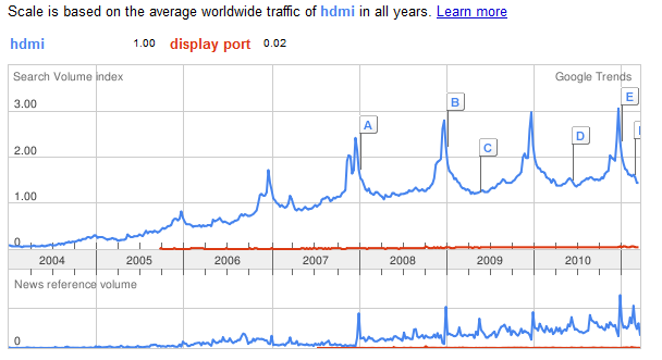
Despite the advantages of DisplayPort for the consumer, HDMI is firmly established in the consumer electronics market, and unlikely to disappear soon. DisplayPort has a number of big companies backing it, including Dell, Apple, and HP, but it may have a hard time breaking into the HDTV world where HDMI currently rules. While DisplayPort’s extensibility and royalty-free nature may eventually bring it to the top, both technologies are likely to be around for at least the next five years.
There’s been a lot of talk recently about how HDMI and DisplayPort compare to one another. As two of the most cutting edge high definition interfaces currently available on the market, they are the subject of intense scrutiny from techies and consumers alike, since it seems likely that one will eventually become the industry standard while the other declines. While similar in many ways, each has some distinct advantages and disadvantages.
Physically and functionally, HDMI and DisplayPort are pretty similar. Both are cable assemblies that work through high bandwidth signalling to provide high definition TV, PC visuals, and gaming, both have fairly similar connectors, and both have some form of content protection. The biggest difference that a consumer would see between the two would be HDMI’s higher resolution capabilities, and the wireless intranet function found in HDMI 1.4.
However, as far as extensibility, convenience, and royalty structure go, the two products are quite different. HDMI products are fairly limited when it comes to extensibility, as newer products are incompatible with previous ones, requiring consumers to update their entire system if they wish to change from an older HDMI product to a newer one. Additionally, HDMI products come in a confusing array of varying qualities, with HDMI 1.4 coming in six different types, each with different aspects, and each requiring a different cable connector. Finally, HDMI has a royalty structure attached to it, with a four cent royalty per unit sold, and a multi-thousand dollar lump sum fee to mass producers. This makes it more expensive to install, which can add up if a consumer has to change their entire system with every update.
Displayport, on the other hand, is both backward and forward extensible, meaning it works with both its older products and those planned for production. It is also compatible with HDMI and DVI technology. Because of its extensibility, consumers are not required to change to a new system in order to update their existing DisplayPort products, which is certainly a plus as far as convenience goes. Finally, DisplayPort is royalty-free and license-free, which makes it cheaper to produce.
Despite the advantages of DisplayPort for the consumer, HDMI is firmly established in the consumer electronics market, and unlikely to disappear soon. DisplayPort has a number of big companies backing it, including Dell, Apple, and HP, but it may have a hard time breaking into the HDTV world where HDMI currently rules. While DisplayPort’s extensibility and royalty-free nature may eventually bring it to the top, both technologies are likely to be around for at least the next five years.
The following snapshot is from 31.3.2011, it will be interesting to see where this goes from here.
Oxygen Free Copper and its Applications
Oxygen free copper is a type of copper that has been refined in an electrically charged solution of copper sulfate and sulfuric acid. This process, called electrolytic refining, causes the copper to have an exceptionally low level of oxygen, often less than one hundredth of a percent.
Commonly used in consumer electronics, oxygen free copper is most frequently found in high end audio-visual systems, though individual oxygen free copper wiring custom cable assemblies are also on the market for the pickiest of music connoisseurs. Oxygen free copper is used for speaker wires, audio/video connector cable assemblies, and amplifier wires because of its purported higher conductivity, and supposedly better ability to transfer low-frequency sounds. Some manufacturers also state that oxygen free copper wiring provides better clarity of sound, and lasts longer than other, less pure, copper wires.
While all of the claims about the good things about oxygen free copper wiring have a degree of truth in them, for most consumers, oxygen free copper wiring is not going to be noticeably different than any other type of copper wiring. The increase in conductivity is minimal, and is not due to the de-oxygenation of the wire. Rather, the process of electrolytic refining also removes other impurities, notably, iron, that can cause resistance. However, even so, the increase in conductivity would not be noticeable unless the wire was extended to a great length, say, over 50 feet. Since no consumer product uses wiring of anything near that length, the increased conductivity is delectably useful at best. In fact, there is no substantial difference between the performance of oxygen free copper and other types of copper in virtually all kinds of consumer products.
Despite its undeservedly high position in the consumer goods market, oxygen free copper does have some applications in very high-tech science equipment, notably, in the construction of magnetometers, electromagnets, and other superconductors. Additionally, oxygen free copper is sometimes used in the manufacture of semiconductors and other high end scientific equipment, such as particle accelerators. In these cases, oxygen free copper is often necessary, as the other components used to manufacture such equipment could have undesired chemical reactions with oxygen.
However, outside of the realm of cutting edge scientific equipment, and extremely advanced copper cable assemblies, oxygen free copper has little practical use, particularly in the consumer world. Though a strong advertising phrase today, it is unlikely to stick around for longer than a few marketing campaigns.
Lean vs Mass Manufacturing: A Very Brief Overview
 “Lean manufacturing” is a favorite buzzword of business conferences lately, and it’s easy for the uninitiated to be unclear on the difference between lean and mass manufacturing. In fact, they differ in many ways, from philosophy and business strategy to production models and company culture.
Lean manufacturing works on the principle of “work smarter, not harder,” and works to eliminate production waste; waste being anything that does not add any value to the final product. Common wastes include waiting time, processing, inventory, and leftovers. By eliminating waste, lean manufacturers are usually able to produce higher quality products in a shorter time.
Whereas mass manufacturing is based off of forecasts and sales, lean manufacturing works off of customer orders. This eliminates the need for warehouses, because little excess product is produced. This also keeps the company from having to sell products at a loss when they become obsolete. The most efficient lean manufacturers report more than twenty inventory turnarounds per year; most mass manufacturers report less than ten.
The culture of the two types of companies differs as well. The hierarchy of mass manufacturing companies is inflexible, and usually produces alienation between employees and managers. A lean manufacturing company has a flatter structure, and encourages broad employee participation, which creates a culture of mutual responsibility and open communication. Additionally, in mass manufacturing companies each employee tends to specialize in one area only, and only works on that particular machine or production area, while those in lean companies are widely cross-trained.
Industries that particularly benefit from lean manufacturing are usually those that exist in rapidly evolving markets or those that require a lot of know-how to produce a quality product. Technological manufacturers are one of those most fond of lean manufacturing, as a large inventory of product can quickly turn into a pile of obsolete junk as the industry changes. For example, a custom cable manufacturer could be left with reels of useless wire, or warehouses of out-of-date custom cable assemblies, which would have to be liquidated at a loss. Also, technological industries like cable assembly companies require a high level of skill from their employees to produce quality products, which can become extremely expensive under the specialist system in mass manufacturing.
Though both types of manufacturing produce results, lean manufacturing is considered more forward-thinking, and is becoming increasingly popular, particularly, as stated, in the technology industry. Although more and more companies are converting to lean manufacturing, large companies will continue to rely on mass manufacturing when quality is not a top priority and they can afford a small seasonal loss.